Homemade Bread, Part 4

Today I am baking the fourth round of bread that I have attempted. Yeast has always scared me, I’m afraid it won’t work right and I’ll end up with a ball of concrete or twigs of concrete, depending. But this has been a year of cooking adventures, and my wife’s bread machine has died, and I can’t go back to store-bought after living on her bread for a while. So my hand was forced.

Part 1 was Joy’s quick white bread. It did OK but didn’t rise well. Good enough to feed me for the week though.

Part 2 was my first attempt at Joy’s classic recipe. I let the dough rise on the stove, and turned the oven on low just so I could maintain the air at 75-85 degrees as specified. I did everything according to the recipe, but the dough was so fry it wouldn’t use nearly the amount of flour that was called for. Again, it didn’t rise right, and the amount of dough that should have made two loaves made only one, which came out in the shape of an alligator head. It was very dense, and actually pretty good, and again it fed me for a week, so that was OK.

Part 3 was my second attempt at the classic recipe. I had talked about it with my wife and she said there was not nearly enough moisture in it, so where Joy called for 1 cup of milk I used 2. Well actually, I used 1 1.2 and the balance of water because I ran out of milk. Then I thought I had better add a little more yeast, so instead of 2 1.4 tsp I used 3. Then, I thought that extra yeast had better have some more sugar to eat, so I added another tsp of sugar. Again I took pains to make sure the temperature was correct, and behold, the dough did rise. I punched it down and left it again, and it rose again. I made a couple of weird looking loaves out of it, and it rose some more. Then I baked it, and it made really good bread. That fed me and my wife for a week, and there is still a bit of it left.

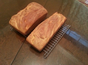
Part 4 is my third attempt at what began as the classic recipe. Since last time I had heard that it really wasn’t so important to maintain the temperature, but that the rising might take longer. Again I used 2 cups of milk, and 3 tsp of yeast, but I forgot to add extra sugar. This may have had a small affect on the rising, but rising did take place. I did allow it extra time because of the lower temperature, which was in the neighborhood of 68 deg F. The two loaves have just come out of the oven and I will try to put a picture with this post – they are nice looking loaves, and when they cool we will see what happened internally.

I was well pleased with the quality of No. 3 and after No. 4 I believe I will proportionately increase the increadients by 25% next time to make the loaves a bit larger.

Homemade Bread 4

This is my fourth attempt at bread.

Homes Of Mine

Home is one thing we all have in common, in one form or another.

Some people live their whole lives in one house. I lived in rural South Carolina for a while and one of the things I noticed was how many old farm houses had graveyards near the house, as if this homestead were meant to be the center of life literally from cradle to grave. Lots of people I met could tell you about great grandparents and before who had lived if not in the same house they lived in, then not far down the road. I heard the history of a big tree where people from the mill that is long gone would be paid. There was a fabric formed of past and present that does not exist in other places I have lived,

Others are lucky to spend more than a few months in the same place. For them time blurs memories of home together. Sometimes details of two or three places are combined, and the composite goes undetected until something causes close examination. There are some notable places that become anchor points in life’s timeline, and the others that, though distinct in reality, merge like stipples on a pen and ink drawing to form a continuum that represents the whole.

The experience most of us have lies somewhere between these two extremes. In the post World War II era the model seems to be that we grow up with our parents in their house, then move into a few temporary places and after a while have a house of our own, where we have our 2 1/2 kids. Not infrequently we move to a bigger house a few years later, then eventually the kids move out and after some time passes we downsize and that’s how we finish. Not everybody gets that experience – in fact, I begin to wonder if that is actually the way things go most of the time, or just a fiction we have created for ourselves with the help of TV and movies.

What follows is an account of the places that were home to me and my family, as best I can remember.

Shadows

My family on my mother’s side is from Virginia and West Virginia. People sometimes think they are the same thing; they aren’t. West Virginia was formed in 1863 out of lands that wished to remain in the Union during the Civil War, or War Between The States. My people are Bouldins and Faidleys, which I have the impression were prominent families. At some point there was a division in the family and the branch that I belong to landed in West Virginia. They were involved in the coal industry as management. I have in recent years heard about the places that were important to  my grandparents and great grandparents and I wish I knew more but I can’t keep them straight in my mind, and I’d rather leave it vague than write things that are wrong.

My father’s side of the family was from Alabama and maybe Ohio. My grandfather went to school in a one room school house and his teacher’s name was Mrs. Shelton. He spoke of her often. Not so often of home and family.

All this has little to do with me – I have no first hand knowledge of any of it. But if I’m going down this road, I have to make at least a nod in the that direction.

269 Oakwood Road, Charleston, WV

In my family there is an era when World War II was over and my grandfather was alive and presided over his family. He had been an officer on a destroyer in the Pacific, the Kilte was its name; it was an old World War I vessel that had been “taken out of moth balls” (my grandmother’s words) and converted to a troop transport. He was present at a number of important battles of that war and I think it served as a dividing point in his life, where the part that came before was separate and distinct from the part that came after. Those who were there think the war years may have been the happiest years of his life.

My mother was born in 1941 and her two brothers were born in the late 40s. Mom always said this was more important than it seems because where her brothers came of age in the Viet Nam era, she became an adult earlier and times changed a lot during that period. She had me in 1963. My grandfather died the same year. He did meet me, but obviously I don’t remember.

Those three lived at least one other place when they were kids, but that house that they all refer to just as “two sixty nine” was where many of the memories were.

I actually saw the house when I was little because my great grandmother lived in a little house next door, which I guess had to have been 267 Oakwood, but that number was never famous. 269 was a big house with white siding and green trim at the end of a long driveway up from the street. It was not at the top of the hill – and that area of the world is made up of hills – but it was close. The address was said to be on the “wrong side of the hill”, because the ritzy houses were on the other side. There was a low stone wall around a good part of the grounds and a big terrace. I know from stories that one uncle raised pigeons there, and they kept their piano on the front porch. There are many stories that I can’t recall exactly, but I remember thinking that the house up the hill was impossibly grand, and wondering what had happened that they left it and how strange it was that new neighbors called the Beanlands lived there now.

I never went in it myself, and years later it burned down.

 My Great Grandmother’s House

I knew my great grandmother as GG because she said Great Grandmother Bouldin was too much to ask a kid to say.

This is the house I just spoke of, that must have been 267 Oakwood road. It was a little house, even to a little kid. When I stamped my foot, by accident or on purpose, the whole house would shake. Actually it was one of the very first pre-fab houses, brought to the site in pieces and erected on a rectangular concrete slab. GG had it put there so she could keep an eye on my grandfather and make sure my grandmother kept a good house. But I didn’t know that at the time.

The house had a living room, guest bedroom, GG’s bedroom, a den, a kitchen, and a pantry/storage area with a little closet where there furnace and water heater lived. All the rooms were tiny but adequate. In the back, attached to the house, was a rusty metal tool shed GG called “the annex”. For years I didn’t know this was a joke, I thought that was what tool sheds built onto the house were called.

In the beginning of my memory, about 1966, my great grandfather was still alive. He always sat in a chair in the den and watched football on the black and white TV, and in his pocket were butterscotch candies that he would offer to me. “Always” probably means once or twice; to kids and dogs, if you do a thing more than once, that’s what you do, and you’ve always done that. He died very early on, which was not made a big deal to me as is proper, but I felt like I had missed something because he was there, and then he wasn’t.

GG had a caste iron skillet. It was a big skillet, bigger than you will find today, and she was a tiny woman. She would make me sausage and fried apples in that skillet on her tiny gas range. Toast came from a new contraption called the toaster oven. She believed that children must have milk and so I did – and spilled it at least once. GG told me milk was good for linoleum in a voice so serious I believed it as gospel truth for years until the kindness of it dawned on me. As I sat at breakfast the window to the back yard was behind me so GG could watch the birds which she scientifically fed suet and seed and hummingbird fluid (?). There was of course a thermometer in view – a big chunky 1950s thermometer that probably actually had mercury in it. Inside on the sill was one of those barometers that is a little house with two doors and an appropriately dressed figure comes out of one of them if it will be rainy or fair.

My Uncle Bob (great-great uncle?) liked cigars and he smoked a lot of them. I don’t know if I ever met him except in passing – the importance of his cigar smoking to GG’s house was that it resulted in a lot of cigar boxes, which she labeled with a black El Marko marker and used to store useful things. My great grandfather’s many pocket knives. String and tape. RIT dye. Nuts and bolts, in no particular order except that they were all things with screw threads. male or female. All my life when I have thought of organizing things I have thought in terms of those cigar boxes.

There was a drawer in the bottom of a chest in that house where there were toys. These toys were all at least twenty years old at the time. Metal cap guns with no red ends on them and leather holsters. Weird games. A little hand held garment vacuum which, of course, I disassembled – first centrifugal fan I ever saw. Then, surprisingly, I reassembled it and it still worked. But my favorite thing in there was a “game” that involved using a submarine to blow up a generic warship of some kind.

The Submarine Game

That game was a great invention, though the premise would horrify modern parents, and I logged a lot of hours on it, so I will go into some detail about it.

The submarine was made of green plastic, thick and brittle like plastic was for a while. Its shape represented the part of a submarine that might be above the waterline when surfaced. It had a hole in the front of it into which you could press a steel “torpedo”, which was a cylinder about 3/8″ diameter, 2″ long, rounded on both ends with a groove in the middle to catch on the trigger of the submarine. The submarine had a spring inside, which would propel the torpedo once released, and a metal catch or trigger that stuck out from the side of the submarine.

The ship’s heart was essentially a mousetrap that would make the ship “blow up”. The spring wasn’t as strong as a real mouse trap, so it wouldn’t hurt a guy very much if he snapped himself. You would set this mouse trap by rotating the metal wire trap part 180 degrees in the vertical plane and securing it with a catch that, when set, stuck through the side of the hull, ready to be struck by the torpedo. When the trap was set, you would lay a hard pasteboard deck into a recess in the plastic hull over the trap, then set some really simple plastic pieces representing gun turrets and superstructure on the deck and there would be your destroyer or battleship or whatever you needed it to be. In time the stock pieces were “enhanced” with wooden blocks like all kids had to play with. (Do they still have those?)

With the torpedo tube loaded and luckless ship assembled you were ready for action. Sight down the ridges on top of the sub and fire the torpedo! It would scoot across the carpet for a good four or five feet. There would be misses, and partial sinkings involving a gun turret falling into the “water”, but eventually the catch would be struck and up the deck would go with everything on it. Repeat the process until the next meal occurred or it was decided that outside was a better place to be for a little while.

Once the torpedo was lost, and my 80 year old GG and I folded back the carpet and moved furniture until it was found. She was a patient woman. I never officially lived at her house, but I spent a lot of time there and in my mind it was more home than a lot of places that officially qualified.

418 Wimer Ave, St. Albans, WV

This is the place I always thought of as my home. I don’t know what it is to others who have lived there and who live there now, but to me this was my point of origin, the only place that seemed permanent, the place I felt safe and comfortable. My grandmother lived there from 1963 or 1964 until she died several years ago – more than forty years. I lived there  officially only five years, from 1964 until 1969, and for one more year later, 1977. From my perspective today that seems like a significant but small patch of time but in my memory those years were infinite, as time is to kids.

The House And Grounds

I am going to guess that the house was 1700 square feet. The square footage of houses is reckoned different ways by different people, but I reckon it as the sum of the square footage of the rooms in it, excluding closets, staircases, utility room and of course walls, chimneys et cetera.

The house had two stories plus a finished basement and a minimal attic. It was built on a hill so that the front exposed two stories, but the back exposed those two stories plus the basement. At the rear of the house, built onto the exterior basement wall, was a screened in porch.

If you stood on the front porch in the middle of the house, the front yard was bounded from left to right by these things –  the driveway, which led into the garage built onto the side of the house; the street, next to which was no sidewalk; a walkway perpendicular to the street, which led to “the back stoop”, a roofed concrete landing on the right side of the house; and the front of the house. There was a medium size tree in the corner of the driveway and the street, and a small tree in the corner of the street and the walkway.

If you looked out over the hill at the back of the house having just come out of back door from the basement, the back yard was bounded from left to right by these things – a chain link fence with a gate that opened onto concrete stairs leading to the front yard; more chain link fence at the bottom of the hill, overgrown with honeysuckle; chain link fence coming up the hill on the right until it was spliced to a rectangular patterned wire fence than continued until it met with the rear outside corner of the garage. Near the house on the left was an apple tree that produced June apples from which my grandmother made apple sauce. Near the bottom of the hill were two or three other apple trees, and the wire fence at the top of the hill had several fairly tall pine trees next to it. At the bottom of the hill was a stone retaining wall which had proved not much good at retention, and for a while in the middle of the hill stood a brick barbecue on a concrete pad with a brick patio in from of it. The bricks and the barbecue were later removed and the area became a flower bed.

As I write these things they go onto the page as a catalog of physical features but to me each one of those features is full of significance, attached to memories of childhood when the sun was warmer, the air was cleaner, everybody’s cards were on the table and life was simple and good- a world that existed only in the mind of the child that I was, a world created for me with care by my family. Everybody does not  remember a world such as this. I am grateful that I do.

Back To Blogging

I haven’t written anything here for a while because I’ve been focused on learning stuff at work and at home. But today is the start of my Christmas holiday, so I am going to try to add the things I wanted to add.

My first step in this process was to make a page for “my” scalloped potato recipe. It’s really the best thing that I make, and I’d like you to be able to make it too. The cool thing about it is that you don’t have to make a sauce, which saves on dishes, time and aggravation. Take a look at it!

Pancakes And Bacon

I made pancakes and bacon for my wife and myself this morning, and took the opportunity to add this recipe to my little collection of pages. I was so happy to be able to cook today! Earlier this week our sump pump died and our basement flooded – not too much, but enough to take out the furnace and water heater temporarily. It took until yesterday evening to recover from that.

So today, I am really glad to wash dishes and make food and generally return to business as usual.

Check out my pancake recipe, it’s more involved than Bisquick but still pretty quick, and I think the extra effort pays off.

Inkscape: Engineering Computation Sheet

For the years I spent designing mechanical things, I liked to do calculations and sketches on a computation pad. At some point I realized that lots of people use these because they are required to do so by the organizations to which they belong. I started doing it because of the unique nature of these pads: the grid is printed on the back of the sheets, and it shows through to the front clearly enough to use but faintly enough not to interfere with a sketch or neatly organized figures. A border is printed on the front, with spaces for descriptive information about the subject of the sheet, who did it, and so forth. It’s well thought out and the sheets can stand up to the hostile plant environments where my sketches were generally made.

I still use these pads in the real world, but I thought it would be neat to have one in the world of Inkscape, so I started one this weekend.

Since we are in this wonderful electronic world, there are some things that can be done that I could only wish for on paper. It would be nice if there were different grids to use – isometric, axonometric, perspective for sketching, log grids for plotting things that benefit from that, maybe a polar grid…

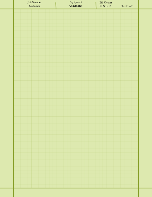
These are all great things, and I will do them in time, but for now I have just duplicated the original, and I thought I would explain what I did. So to begin, here’s my creation:

Calc Sheet

Engineering Computation Sheet

To get this, I took the default layer and used it to make a rectangle of the right green color, then placed the border on it at 100% opacity. I saved and locked this layer and called it Border. I then created another layer on top of it, where I placed the grid.

This is where the little project that should have been simple became a little complicated.

Inkscape provides us with a couple stock ways of making grids that are printable entities, and one grid entity that is a law unto itself. I usually use a grid, but for this project I wanted my grid to be visible on a printed version and useable for reference. So, I tried the tool that can be found under Extensions > Render > Cartesian Grid. This is a very versatile and complex tool, but it does not converse directly in inches but rather in pixels, which do not nicely convert to inches. Since this is to be a grid, I am not interested in accumulating round-off error, so I didn’t use that tool. (I did explore it a little though, and you should too – it has some really neat capabilities.)

There is another tool, Extensions > Render > Grid that is simpler, but still pixel based, so I didn’t use that either. To me, this one seems to have limited usefulness.

What I finally did was to draw one set of horizontal lines – five minors at .25 mm width and one major at .75 mm width, spaced 0.2″ apart – with the pencil tool. That’s how the pad is, and it’s always been the one thing I don’t particularly care for about it, but so it goes. Once I did that I was able to select all 6 lines and group them. This enabled me to tile them without setting any tricky offsets – I set up for simple translation, using 10 rows and 1 column, and that generated the horizontal lines of my grid using Edit > Clone > Create Tiled Clones. You will realize pretty quickly that one of my minors overlaps the major of the next tile, so there is line-on-line. I could have ungrouped everything and got rid of these, but I didn’t.

I used a similar process to get the vertical lines, only I set up for 1 row and 7 columns.

Next, I released all the clones with Edit > Clone > Unlink Clone. I then selected all of the grid lines and reduced the opacity to 20% to give the grid the appearance of showing through the paper. I think I ended up with a pretty good likeness of the original.

The last thing I did was to save and lock the Grid layer and make a new layer called Title Info. On this layer I put text in the places I usually fill things out, justified as seems proper. I thought a while about the right font to use. I would like to have found one that looks like lettering with a mechanical pencil or technical pen – one that would tolerate using “all caps” well. I think I could have found one, and I may yet use it for myself, but I didn’t want to use anything that most people might not have. So I settled on Garamond, which is nice but not exactly at home on a calculation sheet. I guess Arial might have been better but I’m tired of that right now.

When I can get the capability in place, I’ll make this and other files available for download as Inkscape SVG – but if you are inclined to whip one of these up in the mean time, I think this should be enough information to do it without the fumbling that I did.

Because I have the grid on its own layer, I can add those other grids I want on their own layers and toggle between them. If it suits me, I can turn the grids off altogether for any given sketch.

Inkscape: How To Draw A Room In Two Point Perspective

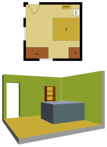
If you have a plan view and at least a couple of elevations, you can whip up a two point perspective view of a room without much trouble.

You will want to know how to set up a two point perspective drawing with horizon, vanishing points and measuring points how to use those things. If you need a quick reminder, you can see my previous post on how to construct a cube in two point perspective.

Setting Up

Here is an overview of the perspective setup:

perspective1

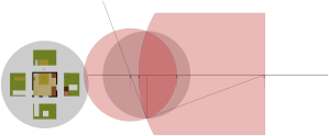
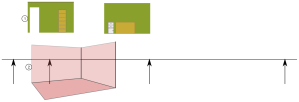
I used a circle that entirely encloses my plan and elevations as a 90 degree cone of vision. I like to stay within 60 degrees, but I expect the perspective to be well within this circle. I chose a corner orientation that I think (hope) is going to turn out pretty well, then laid out my measuring points.

Constructing Planes For Walls And Floor

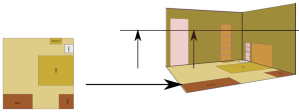
I want to view this room as if I were standing, which I will say would put me eye about 5 ft off the ground. So, I put copies of the elevations in accordingly and constructed the walls and the floor:

perspective2

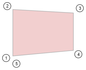
Copies are free, and you’re going to want your original later! So make copies of your elevations. Note that the horizon line is at eye level, and I put in the walls in such a way that they appear to have been folded out from the perspective view. I struck lines from the measuring points through the corresponding wall corners to lines projected from the main corner (which also happens to be at the center of vision), to the vanishing points. Where these measuring lines intersected the projected lines defined the room corners in the perspective view. I then made paths connecting the four corners of each perspective wall, always starting with the bottom left corner.

Finally, I projected lines from the vanishing points through the floor corners to define the near point of the floor, and then created a path to define the floor.

Mapping The Walls To The Perspective View

Now we get to use a really nice tool that Inkscape provides, which will take our elevations and plan view and fit them to the perspective view. To get this to work, we have to do things a certain way. I mentioned creating the perspective faces always starting at the bottom left – here’s a little diagram of how you have to draw these faces:

Perspective Face Pick Order

Now I’ve done three of these already, and maybe you have too. I hope you did them in the right order, but if you didn’t, it’s no big deal to recreate them. So, now that you have your faces created the right way, move your elevations out of the way. Then, select first the elevation, then the plane it’s going to map to:

pick for perspective command

Now select the menu option Extensions > Modify Path > Perspective. If you’re really lucky, you’ll get this:


If you’re not so lucky, maybe you left some things behind, or your elevation is upside down or backwards or both.

 If you have trouble taking everything with you, undo the perspective command. Make sure everything you want to take is grouped, then select the group. Pick Paths > Object To Path. Now deselect, make your selection for the perspective command, and execute it again.

If you had orientation trouble, you probably haven’t got your face built quite right. Back up and try again. Once you get the hang of it you’ll never miss – and this command makes it a lot easier t build the perspective view.

The other wall should present no problem, but the floor has a slight twist in that you have to take the walls off before you map it to get an accurate view:

Floor Mapped

Here you see the “naked” floor – note the orientation you have to have – and the result. You can see that even the labels have been put in perspective! Meditate on that for a moment – there are some nice possibilities there.

Making The Furniture

Now we are in a position to make the furniture – we’ll quickly build the bed, the bookcase and the bedside table. You will be glad later if you put each of these on its own layer – then you can toggle them on and off at will.

The Bookcase

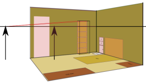
Use the left vanishing point to project the top edges of the bookcase. Use the footprint on the projected plan view to bring up two verticals from the front of the bookshelf. Connect the dots, and you’ve got the basic shape:

Bookshelf Frame

Now bring up a copy of the bookshelf elevation by itself, make a face on the front of the bookshelf, and map the elevation onto the front perspective:

bookshelf wireframe

That’s all you’re going to need to build faces and finish the drawing:

bedside table in place

Now, with a similar procedure you can put the front on the bedside table and fill in the sides and the top, and even more easily, outline the bed.


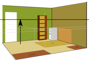
Apply a couple of faces to the bed and your done building furniture. Then, add some depth to the doorway and re-lay the floor without the extra furniture and we can call it a day:

bookcase finished

OK, the “Bed” took a left turn somewhere due to my eyeballed dimensions, but the concept is there.

Of course this is a really simple example but I hope this demonstrates how you can get a pretty good start on a more serious drawing using Inkscape’s perspective tool and a little preliminary drawing.

Inkscape: How To Draw A Room To Scale

It is not very hard to draw up a room in Inkscape, but I would like to present some ideas that may be helpful in the process.

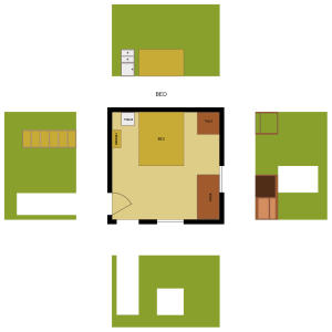
To begin with, a plan view is essentially a picture of an object from the top down. Elevations are views of an object in a plane perpendicular to the ground, i.e. front, side, East, North. These are generally drawn to some kind of scale such as ¼” = 1’-0”, although the notion of scale has become a little cloudy in the computer age.
plan and elevations 1_48

In CAD, it is usual to draw everything full size and it used to be usual to scale up the drawing border so that when the drawing is printed on paper, it is at ¼” = 1’-0” (or whatever scale you draw to). Text and dimensions are geared to work this way. Not exactly so in Inkscape.

I drew this room full scale in Inscape and got away with it. But I wouldn’t have got away with doing a whole house, because Inkscape has a maximum canvas size. Since I did get away with it, I scaled my views down by a factor of 1/48, because there are 48 quarter inches in a foot. I am hard headed about drawing to a scale that is found on a physical architect’s scale; 1/50 would have been nicer.

To begin with, I set my grid up to be one square per 6” with majors every 4’. This is just convenient, and I wasn’t going to use any odd sizes for the sake of simplicity. I set my snaps to intersection, center of rotation, endpoints, and the grid.

I drew the plan view first, drawing in my doors and windows and making the walls arbitrarily 6” thick although they aren’t really. I traced the solid bits and filled them, then erased the construction lines, then threw in a scuare for the floor.

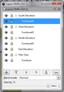
My layer structure is like this:

layers for plan and elev

There should really be a furniture sublayer for the East Elevation as well, but there’s not.

After the plan view was done I roughed in some furniture and labeled it.

Then, I did the elevations. As you see, thes are not oriented in the traditional way with the ground at the bottom of the page and the ceiling at the top, but as if there were a cardboard model of the room and the walls fell down outward. This makes projection easy and is quite clear to me – I saw an architect do it somewhere, and stole the idea.

As I said, I laid this out full size and scaled it, but here’s another aggravating limitation: there are only 3 decimal places in your scale factor in the Transform dialog. That means I’m not exactly at ¼” = 1’-0”, and if I had it to do over I would make a bar scale. I would also make a north arrow just on general principles – but you can benefit from my 20-20 hindsight and put those into your drawing if you want.

I made use of grouping and subtracting paths to keep my number of entities very small and manageable.

Now, you are going to notice that for instance a door is 6’-8” tall generally, and that isn’t on the grid. I connected the sides at the “Bottom” of the elevation, then used the Move part of the Transform dialog to get my 6’-8” spacing.  If I did it again, I would make a rectangle and use the Scale tab, set to inches, to set the size exactly, then move it into position.

When all was finished, I saved the image as it was (full size), then saved a copy and scaled that. Copies are free, always leave a trail of breadcrumbs back to important forks in the road.

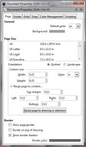
Finally, you will probably want the image in some kind of format that plays well with other software, maybe PNG. If you go and make one of these having scaled the image down you get… unexpected results – a tiny little geometry, or NO geometry.

What you want to do is go to the Document Properties and use the Resize Page To Drawing feature:

resize border

Note that this is also the place where you set up your initial grid, if you didn’t notice. The grid won’t print or transfer to any image you create.

Once you have resized the image, all should be well. You can make a PNG or other format using Save Copy As, and the result will be your version of my plan above.

Happy Inkscaping!

Dear Autocad: Days Of Lines And Circles

Dear Autocad,

I brought you onto my computer in your current incarnation yesterday. You came with a bunch of strangers that are now spread out on my desktop like a bunch of passed out sorrority girls – mudbox, sketchbook pro and a bunch of others as well as you and your buddy Inventor.

When I opened you up I saw that you’ve been hanging around with MS Office ‘way too much. You’ve got your own ribbon, although it toggles pretty easily, and you’ve done something with my command prompt. You’ve got strange notions about making bills of materials kind of like Inventor does, although you can’t really do that because you’re not 3D. (Not really. Sorry.)

You’ve got all kinds of fancy image tools now, and a host of other things. When you and I parted ways you were trying to have model space and paper space and do solid modelling. You tried to dress up like a constraint based solid modelling package with Mechanical Desktop, which I actually thought was pretty cool and worked well enough, although it was anything but seamless.

When I met you, you were on Release 10. You were also my last, best hope for a decent career. I spent my last dime and a few more to learn to drive you. Almost immediately I discovered that what I had bought was access to you – the instruction was a joke. So we went round and round. I learned, just type what you want to do. Line? Line! and then lots of options. Circle? Circle! and then more options then really advisable. Then there’s arc, but I used linelinecircletrim faster than I could negotiate that one.

And when it came time for dimensioning, holy crap! Who knew there could be a thousand system variables associated with putting a dimension on something.

Then there was AutoLISP. Lost in stupid parentheses. I spent more time than I should have trying to automate everything, but came up with some pretty cool stuff too. Everybody had their little stash of routines.

We drew everything full size, and made our border big enough to fit what we drew, then set up the plotting to get it back onto a piece of paper.

And when we could draw everything that we could draw with a pencil, including isometrics with your cool iso snap options, we played around with your 2 1/2 D. Lots of faces, origami “solids”. Some weird stuff with meshes. But then we got back to work.

We could construct anything because of your infinite (well nearly infinite) precision. You were a 2D drawing machine.

Of course you would crash without warning, so I learned to save often, and enough people did the same that you grew autosave.

So because we went through so much together I feel like I can tell you, stop putting on airs and pretending you’re something you’re not. What you are is the most awesome computer mechanical drawing tool ever invented and one of the few still standing. Nobody can touch the tools you evolved for drawing stuff in 2D. Inventor, for all its power, still can’t make a reasonable rectangle – to – round transition pattern. That’s for you and me to do. So, be that. You can’t beat Inventor or Solidworks at their game, or Photoshop or Illustrator at their game. But they can’t touch you at yours.

And now if I can just get you to turn my spreadsheet into lines and text like you used to before your 30 day visit is up, I’ll be happy.

Best of luck,

Bill

World Book Lives On: A Really Quick Tour Of Layers In Inkscape

Once upon a time, in a world where databases were on 3 x 5 cards and knowledge came in large part from a printed page that interacted with the reader mainly by occaisionally cutting his finger, kids like me were required to write reports on various things and the substance of those reports came mainly (sometimes completely) from the World Book encyclopedia. Encyclopedia Britannica was probably more complete, but World Book had these cool articles, famously the frog diagram but also as I recall human anatomy and physiology, that were accompanied by acetate overlays adding more and more detail to the paper base drawing.

The base drawing might be just the outline of the frog, or a guy (or gal) in the anatomic position. These clear plastic sheets could then be put over the base to add detail. My memory is not clear as to whether World Book’s overlays were attached to more than one edge of the page, so that overlays could be applied independently of their sequence, but I have seen that done, as well as seperate sheets with registration marks to make sure they are properly aligned with the base.

Hours have been spent looking at those things, whether or not they were relevant to the job at hand.

Times have changed and then changed again. Many years ago I started to learn Autocad; layers were, maybe still are, a very important part of the anatomy of an Autocad drawing for a number of reasons but chiefly I was struck by the notion that now I can create illustrations just like the ones in those those World Book articles.

Well, layers allowed you do a good deal more than that in Autocad, and after the passage of even more time, they allow different if not more things to be accomplished in Inkscape.

What You Can Do With Layers In Inkscape

I am no great master of Inkscape, in fact I am learning as I write. I was a draftsman for a big chunk of my career and my approach to graphics-related software tends to use my CAD and board habits as a point of departure. But Inkscape ain’t CAD.

Suppose you want to construct a figure from objects available in inkscape. If it were a piece of paper you were working on, you might make some light lines that would locate the permanent elements and define their edges, or the limits of their features. The drafting rule is, make these so light they are invisible at arm’s length. I suppose in art you want to do away with them completely or do your constructing on scrap paper and transfer the result to your main work. But in Inkscape, you can make these lines and circles boldly and without fear of being unable to get rid of them when you want to.

If you use a construction layer for your construction lines, you can have these layout lines when you want them, and make them go away when you don’t. If you use sublayers within your construction layer, you can make complex constructions on each of those, and turn them each on and off at will.

If you have several elements on an image, you can put them on different layers and work on one without harming the other, or cause one to interact with another in special ways.

There are lots and lots of reasons to seperate groups of objects onto layers, but in the end it all has to do with organizing your image. And since I promised to be brief, I’ll leave it at that.

The Layers Dialog Box

The layers dialog box is at Layers -> Layers, shortcut Ctrl+Shift+L.

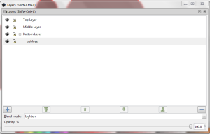
Inkscape Layers Dialog

Apologies for blurry screenshot – haven’t figured that out yet

The Grid

When you bring up the Layers dialog, a grid presents itself showing the names of all of the layers in the image, their relative positions, and the states of two important properties:  visible and locked.

Each layer has a name. Experience may show you that these names should conform to an overall scheme and be logical and consistent – but they don’t have to be. That is for you to decide. When you click in the Name box, you can edit the name.

The relative position of the layers controls the way objects are displayed. If layer A is above layer B, then objects on layer A will cover objects on layer B. This can be useful, and can be annoying, as is the case with anything that is totally within our control.

Locking and unlocking a layer has the effect of preventing or enabling changes to the objects that are on it. This is a great way to keep yourself from accidentally moving or changing things that are done and will allow you to work with construction geometry without having to be careful about moving it.

Visibility is just what it says: when a layer is visible, the objects on it are displayed. When visibility is off, those objects are not displayed. When a layer is invisible, you will be able to select objects on it and move them accidentally.

Birth, Death, and The Changes In Between

Underneath the grid is a row of six buttons. The first button adds a layer, the last button deletes it  and the following buttons move it all the way to the top, move it up one layer, move it down one layer, and move it down all the way.

One important thing to note that is not immediately obvious: you can define sublayers by chooosing the “Add As Sublayer” option when you use the plus sign. This creates a layer that is turned on and off, locked and unlocked with the parent layer, but can also be controlled individually.

Blend Mode

Blend modes are available in a combo box below the row of buttons just described. They apply a filter to all the objects on a particular layer. I honestly haven’t used them, but I can see how they would be useful: for a quick treatment of the subject, look here: http://books.google.com/books?id=P1qqeWc5t5QC&pg=PA289&lpg=PA289&dq=inkscape+layer+blend+mode&source=bl&ots=u0ih5U1Nno&sig=utdYRhkqefm_lg7wEXUypUJdod4&hl=en&sa=X&ei=hspsUsebKovrkQfHroDQAQ&ved=0CHAQ6AEwCQ#v=onepage&q=inkscape%20layer%20blend%20mode&f=false.

Opacity

Opacity is a measure of how thoroughly an object covers an area. When an object has 100% opacity it completely covers objects below; with 0%I, it is invisible. Between those extremes, the fill color and the stroke color behave like stronger or weaker washes, or as colored acetate films if you like – play with them a little and you will see.

In Inkscape, you can apply opacity at the object level or to an entire layer. In the layer dialog, there is a slider at the very bottom of the box that takes care of opacity. You can also set it numerically with a text box to the right.

It is interesting that if you already have a medium opacity set for a few objects, and maybe full opacity set to others on the same layer, and you adjust the layer’s opacity, the layer setting affects the entire layer, but not the way objects interact with each other on that layer. So, if you have an opaque object covering part of another object on the same layer, and you adjust the opacity of the layer, the bottom object remains totally covered by the top object; but both objects will only partially cover an object on a layer below.